Table of Contents
What is PWM?
Pulse Width Modulation (PWM) is a powerful technique used to control analog devices with digital signals. Since microcontrollers like Arduino can only output digital signals (0V or 5V), they use PWM to “simulate” intermediate voltages by switching the signal ON and OFF at a very high frequency.
Core Components of PWM
To analyze a PWM signal, we look at three main factors:
Duty Cycle
The Duty Cycle is the percentage of one period in which the signal is HIGH () This determines the average voltage delivered to the load.
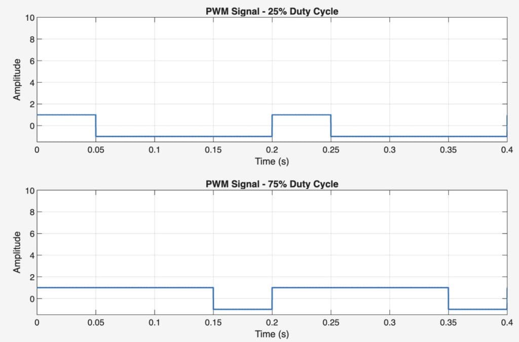
Low Duty Cycle (e.g., 25%): The signal is mostly OFF. Low power/brightness.
High Duty Cycle (e.g., 75%): The signal is mostly ON. High power/brightness.
Compare two graphs that has different Duty Cycle. Also, you can try out by coping the Matlab code below.
clc;
clear;
close all;

% Parameters
f = 5;                 % PWM frequency (Hz)
T = 1/f;               % Period
t = 0:0.0001:2*T;      % Time vector (2 periods)

% Duty cycles
D1 = 25;               % 25%
D2 = 75;               % 75%

% Generate PWM signals
pwm_25 = square(2*pi*f*t, D1);
pwm_75 = square(2*pi*f*t, D2);

% Plot
figure;

subplot(2,1,1)
plot(t, pwm_25, 'LineWidth', 1.5)
ylim([-1.5 10])
grid on
title('PWM Signal - 25% Duty Cycle')
xlabel('Time (s)')
ylabel('Amplitude')

subplot(2,1,2)
plot(t, pwm_75, 'LineWidth', 1.5)
ylim([-1.5 10])
grid on
title('PWM Signal - 75% Duty Cycle')
xlabel('Time (s)')
ylabel('Amplitude')
Average Voltage
The average voltage output can be calculated by multiplying the peak voltage () by the Duty cycle ().
From below graphs, you can easily look how has changed depending on the Duty cycle ().
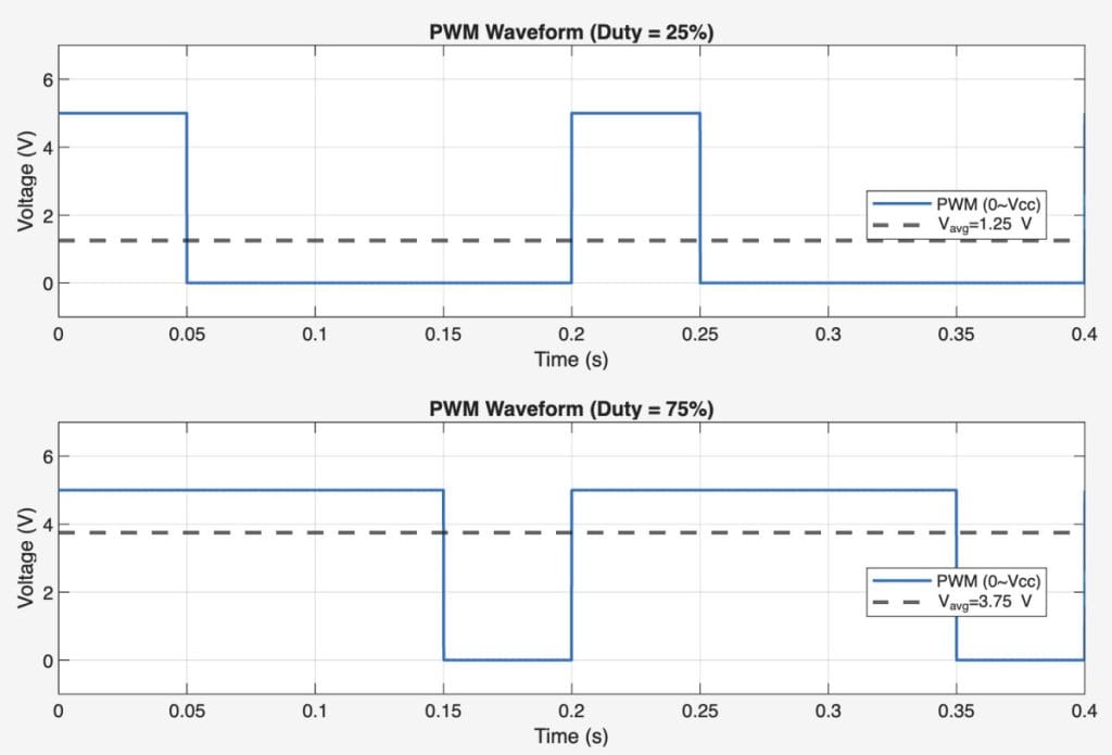
Try changing the Duty Cycle and see how Vavg looks like using below codes
clc; clear; close all;

%% Parameters
Vcc = 5;          % Peak voltage (V)
f   = 5;          % PWM frequency (Hz)
T   = 1/f;        % Period
dt  = 1e-4;       % Time step
t   = 0:dt:2*T;   % 2 periods

D_values = [0.25 0.75];   % 25% and 75%

figure;

for i = 1:2

    D = D_values(i);

    %% Generate PWM
    phase = mod(t, T);
    pwm = Vcc * (phase < D*T);

    %% Average Voltage
    Vavg = D * Vcc;

    %% Plot
    subplot(2,1,i)
    plot(t, pwm, 'LineWidth', 1.5);
    hold on;
    yline(Vavg, '--', 'LineWidth', 2);

    ylim([-1 7])
    grid on;
    xlabel('Time (s)');
    ylabel('Voltage (V)');
    title(sprintf('PWM Waveform (Duty = %.0f%%)', D*100));
    legend('PWM (0~Vcc)', sprintf('V_{avg}=%.2f V', Vavg), ...
           'Location', 'best');
end
Frequency
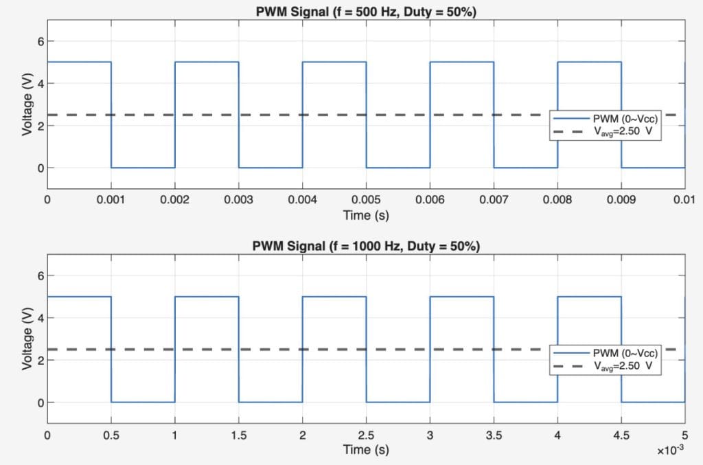
The Frequency determines how fast the PWM cycle repeats. For most LED or motor applications, a high frequency (e.g., 500 Hz to 1kHz) is used so the human eye or the motor does not notice the switching.
Observe how the PWM waveform changes when the frequency is modified. You may notice that there is no change in the average voltage because the duty cycle remains the same.
Real-World Applications
LED Brightness Control
Instead of changing the actual voltage, PWM flickers the LED so fast that the human eye perceives it as “dimming.” This is more efficient than using a resistor.
Servo Motor Control
Servos use a specific type of PWM. The Pulse Width (usually between 1.0 ms and 2.0 ms) tells the servo exactly which angle to hold.
Motor Speed Regulation
By varying the duty cycle, you can control the speed of a DC motor without losing torque, which is essential in robotics.